
I felt that after the last big scientific post “Would A Tibia Subjected To High Intensity Dynamic Mechanical Tensile Loading Fracture Or Elongate Through Stretching First?” I had to write a final, conclusive post on explaining whether the idea of bone stretching is even possible.
At this point, if one is looking for a yes or no, question, I would lead to the side that says that bone stretching is probably not feasible. This means that all of the previous efforts by other height increase seekers were probably never supposed to work. I wanted to give a personal interpretation on some engineering principles I learned years ago to show why the idea of pulling on the bone most likely will not result in longer bones, just broken bones.
Let’s look at the mechanical engineering or materials science explanation of what is known as the Youngs Modulus concept. In addition, we look at the engineering concepts of stress, strain, plastic deformation, brittleness, stiffness, elasticity, and a whole lot of other Materials Science & Engineering basic concepts.
Note: One of the focuses in my undergraduate degree was in Material Science so I might wish to talk a little more about the engineering aspects and the calculations than the average height increase researcher or height increase seeker might wish for.
Along the way I will be combining all of the terms above to dissect the diagram of the stress – strain curve, the Modulus of Elasticity, tensile strength, as well as the Yield Point aka Yield Strength aka Elastic Limit.
First of all, I am proposing that the reason we are even talking about mechanical engineering & material science concepts is that we are hoping to eventually figure out how much of a load (aka force over area) we would have to apply in a tensile way to pull the average adult male human’s femur bone to a point where it will stretch out, where the bone will not just spring back to the original length, and that the bone will not fracture or break in a critical way, hopefully.
From the older posts…
- “The Values For The Magnitudes For The Forces And Loads Needed To Increase Epiphyseal Cartilages Thickness And Human Femur Bone Without Fracture (Important)“
- “Long Bone Tensile Strength, Loading Capacity, Compression Strength“
- “Is Bone Distraction Or Bone Breaking Always Needed To Increase Height?“
- “Sky’s Mistake, Why He Never Increased In Height“
I will be referencing and using as a guide to write up this post.
The scientific studies and articles I will be citing are…
- “DIFFERENCES IN THE TENSILE STRENGTH OF BONE OF DIFFERENT HISTOLOGICAL TYPES“
- The Wikipedia article on Human Bone is also cited for reference
- Bone Development and Structure
- Mechanics Of Bone
So the million dollar question is, what is the load in units of Newtons/meters^2 or Lbs do we need to really pull the bone apart to a point where we do get plastic bone lengthening which is not just elastic and will snap back to the original length when we decrease the load?
In a very recent post “The Values For The Magnitudes For The Forces And Loads Needed To Increase Epiphyseal Cartilages Thickness And Human Femur Bone Without Fracture (Important)“ I had using two major assumptions and guesses calculated the value of the needed load to be 20,000-30,000 lbs of force needed to create the needed force over area to pull the adult human femur bone apart, resulting in either fracture or plastic deformation.
For the reader, this would seem extremely high. The fact that most normal average sized 4 door sedans weight around 2500-3500 lbs shows just how large of a weight would be required to stretch out a single adult male human femur bone. It would require around 10 of these cars put together on a scale before the bone is supposed to snap beyond the elastic range.
So what exactly are we talking about when we keep on talking about these terms called stress, strain, loading, forces, tension, tensile strength, etc? Let’s go over some basic engineering principles.
Engineering Principles Of Stress & Strain & the Stress-Strain Curve
The concept of stress has the units of Newtons/meters^2 so it is the same idea as pressure. In the field of engineering mechanics, the concept of stress refers to “…the internal forces that neighboring particles of a continuous material exert on each other” (Wiki)
From the website Efunda.com…
“….The stress field is the distribution of internal “tractions” that balance a given set of external tractions and body forces.”
For our application, we are only looking at what happens to an object when being pulled in opposite directions along the axis which can be simplified aka idealized into a long cylinder (I think a human femur sort of look like a cylinder) for easy calculation reasons. So from the Wikipedia article on the different types of stress…
“Stress is defined as the average force per unit area that some particle of a body exerts on an adjacent particle, across an imaginary surface that separates them.
 Being derived from a fundamental physical quantity (force) and a purely geometrical quantity (area), stress is also a fundamental quantity, like velocity, torque or energy, that can be quantified and analyzed without explicit consideration of the nature of the material or of its physical causes.”
The way to view stress is basically a force of a certain magnitude being applied across the area of the bone. We are looking at the pulling effect. We can even use the term “load”, “stress” or even “force” interchangeably since the way we set up the system for engineering analysis is very simple. The bone turns into a annular hollow cylinder which is where a smaller diameter of cylinder made of a softer composition is enclosed in a larger diameter cylinder made of a harder material.
From the diagram on the right, the force/stress/load will be pulling at opposite directions.
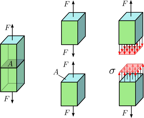 Note: Technically the terms force and stress are completely different concepts in normal physics and engineering situation but our system analysis is very simple so I will be using the two concepts interchangeably.
So the stress is on the axial axis so we can say that the force is tensile. Refer to the picture to the right.
The concept of Strain is a little more subtle. The units of Strain are dimensionless but a look at how the concept of strain is defined reveals what strain is refering to…
Strain = (L2-L1)/L1 where L1 = length of the object having stress exerted on it originally and L2 is the new length of the object from the application of the stress. Another term that is very similar in concept to strain is deformation (for mechanics) and deformation (for engineering).
From the Wikipedia article on deformation using the field of material sciences and engineering, the definition is….
“…deformation is a change in the shape or size of an object due to an applied force….can be a result of tensile (pulling) forces, compressive (pushing) forces, shear, bending or torsion (twisting).”
“As deformation occurs, internal inter-molecular forces arise that oppose the applied force. If the applied force is not too large these forces may be sufficient to completely resist the applied force, allowing the object to assume a new equilibrium state and to return to its original state when the load is removed. A larger applied force may lead to a permanent deformation of the object or even to its structural failure.”
So in a way, the term Deformation and Strain can also be used somewhat inter-changeably in our discussion. Now let’s see what is written up about the term Deformation…
 The thing to note is that there is two difference types of deformation, 1. elastic and 2. plastic.
Elastic Deformation
This type of deformation is reversible. Once the forces are no longer applied, the object returns to its original shape.
Normal metals, ceramics and most crystals show linear elasticity and a smaller elastic range.
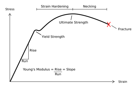
Me: When we look at the graph above, the elastic region is the first part where the stress applied is not that high. The graph shows that as the stress applied rises, the strain also rises, but not at the same degree of change. The change is linear, but since the object or material we are looking at is so hard and strong, the strain, which is the change in length from a tensile force, will be very small while the stress will be very high.
The thing to remember about this graph is that it is not showing something that is happening as a process, throughout time, but something that is happening from repeating testing of different loads aka stresses. There seems to be a upper limit to the amount of stress but there is no limit to the strain. This means that the material at some maximum point will break or stretch out.
Looking at the charge again, we see that using elementary Geometry principles that the term Young’s Modulus refers to the slope of the stress-strain curve. The stress is the variable we chart or graph on the vertical axis while the strain is the variable we chart and measure on the horizontal axis. The slope, which is rise/run is the Young’s Modulus. Intuitively when we try to visualize what the Young’s Modulus would mean from a physical representation point of view, we can say that it is the amount of foce we have been putting on the area of the object over the amount of small length changes that the bone actually goes through. So the larger the Young’s Modulus, the less that the material will deform in the direction that we want.
From Wikipedia….
Young’s modulus, also known as the tensile modulus or elastic modulus, is a measure of the stiffness of an elastic material and is a quantity used to characterize materials. It is defined as the ratio of thestress along an axis over the strain along that axis in the range of stress in which Hooke’s law holds. In solid mechanics, the slope of the stress-strain curve at any point is called the tangent modulus. The tangent modulus of the initial, linear portion of a stress-strain curve is called Young’s modulus. It can be experimentally determined from the slope of a stress-strain curve created during tensile tests conducted on a sample of the material.
Update: 5/11/2013: it would seem that I have new information showing just how incredibly high the Young’s Modulus value is in human cortical bone.
Reference: Rho, JY (1993). “Young’s modulus of trabecular and cortical bone material: ultrasonic and microtensile measurements”.Journal of Biomechanics 26 (2): 111–119.
Values: 14 GigaPascals or 2,030,000 psi
Comparison: If we look at this high young’s modulus versus other compounds on the Chart for Young’s Modulus article on Wikipedia, we find other values like for polypropylene, nylon, rubber, tooth enamel, and different types of steel. In comparison, it would seem that the elastic nature of cortical bone may not be as high as previous expected, if it is true that human cortical bone may just be around 7X the resistance against deformation as polypropylene and only around 20% of the strength of human tooth enamel.
There is two main things to note that is important as well. That is that there is a major different between the Yield Strength and the Ultimate Strength. Sometimes the terms Yield Strength and Ultimate Strength is used interchangeably but I wanted to make a point that for our application, we have to differentiate between the two terms.
- Yield Strength – When the object moves past the range where it would exhibit elastic behavior, where the change in stress levels would correlate in proportion to the effect of changes in the strain.
- Ultimate Strength – This is the lowest limit of what the stress can be and the resultance changes in deformation (aka distraction or lengthening) will happen to any magnitude without the need to increase the stress. For bones, being rather materials, it would most likely be the point where the bone material starts to fracture.
On a personal educated guess, I would think that there is never a truly only elastic effect. There will always be fractures in the bones, just that the fractures are small and microscopic so on the macroscopic level of measurement, we don’t notice the fractures.
Linear elastic deformation is governed by Hooke’s law, which states:

Where  is the applied stress,
  is a material constant called Young’s modulus, and ε is the resulting strain. This relationship only applies in the elastic range and indicates that the slope of the stress vs. strain curve can be used to find Young’s modulus. Engineers often use this calculation in tensile tests. The elastic range ends when the material reaches its yield strength. At this point plastic deformation begins.
Plastic deformation
This type of deformation is irreversible. However, an object in the plastic deformation range will first have undergone elastic deformation, which is reversible, so the object will return part way to its original shape.
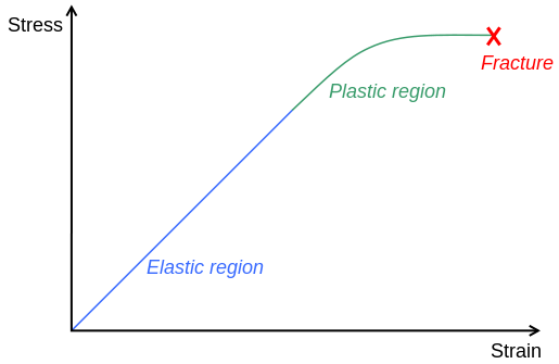 From the same Wikipedia article, we can see another example of the stress-strain curve, but one for a more ductile material.
I would like to note that sometimes the stress-strain curve is drawn differently due to how brittle, elastic, or ductile a material can be.
Brittle materials don’t have a very large range between the Yield Point and the Ultimate Strength point, if any at all. There is no necking or strain hardening.
Conclusion:
This post is to do one main thing, which is to resolve the subject of ever trying to “stretch” or “elongate” the bones using 30 lbs weights strapped to the shins, ankles, or or parts of the limbs. In the posts “Increase Height And Grow Taller Using Ankle Weights , Part I” and “The Thigh Bone Routine Of EasyHeight.Com” I referred to the old height increase researcher Sky trying to pull his bones to elongate them. That didn’t work and he tried for over 5-6 years to find something that worked.
In a recent post I had shown that about 30 lbs is what would be needed to distract the femur bone of a young laboratory rabbit with a lot of growth plate cartilage. That resulted in hyperplasia.
The thing I really wanted to emphasize and to close down the possibility of ever trying a stretching motion using a constant or even linearly increasing load like putting ones leg in a corkscrew device to slowly pull at the adult human leg bone without at least first creating a small fracture or distraction to decrease the amount of tensile load needed dramatically.
I thought I could conclude and state a definitive answer of “NO” for the idea fo stretching bones from writing this article but it seems that more research would need to be done to resolve this issue for good.
Pingback: Lengthening bone via microcracks, why hasn't it work? | Natural Height Growth